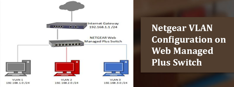
Netgear VLAN Configuration on Web Managed Plus Switch
This blog post is written mainly for readers who are interested in gaining knowledge regarding how Netgear VLAN configuration can be done on web managed plus switch with shared access to the internet. For this type of configuration, the Netgear router that you set up via routerlogin.net should be VLAN aware. The devices in each VLAN do not have permission to interact with devices in other WiFi networks. The reason being, that the inter-VLAN router is not enabled on the wireless router.
In the information given below, we have talked about configuring these:
- VLAN 1 – Network 192.168.1.0 (mask 255.255.255.0)
- VLAN 2 – Network 192.169.2.0 (mask 255.255.255.0)
- VLAN 2 – Network 192.169.3.0 (mask 255.255.255.0)
Prior to reading the information below, ensure that you bear certain things in mind like:
- Keep the IP address belonging to the web managed plus switch jotted on a paper.
- See to it that the software of the managed plus is running on the latest version.
Now, walk through the instructions mentioned further in this blog post and wrap your head around how to go about the Netgear VLAN configuration process.
Netgear VLAN Configuration Process Execution
The configuration process has been divided into five parts. This is so that many other users like you can find it easy to execute it without facing any technical issues.
Create VLAN on Switch
- Gain access to an updated internet browser.
- Double-click on the URL field or address bar and type the IP address of the switch.
- Clicking the Enter button will redirect you to the new window.
- Input the admin password belonging to the switch and hit Login.
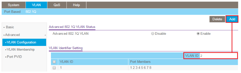
- Select VLAN > 802.1Q > Advanced > VLAN Configuration.
- Set Advanced 802.1Q VLAN to Enable.
- Next, enter the VLAN ID that you wish to create under the VLAN ID field.
- Select the Add button and add VLAN 2 as well as 3.
Add Ports to the VLAN
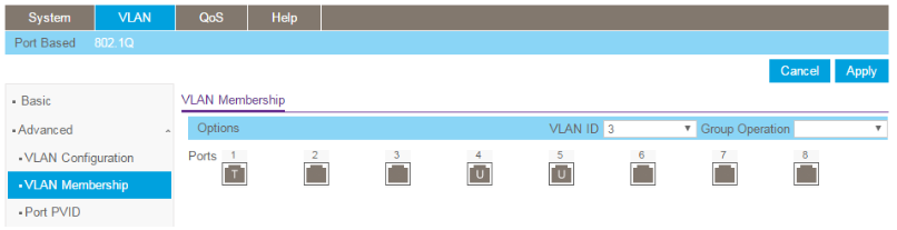
- Select the series of options like VLAN > 802.1Q > Advanced > VLAN Membership.
- Click the drop-down menu by the name of VLAN ID.
- Select the VLAN 2 option.
- In some time, Port 1 will join the router and should be tagged in VLAN 2.
- Click on port 1 and wait for a T to appear in it.
- Soon the 2nd and the 3rd ports will connect to the devices.
- For your information, they ought to be untagged in VLAN 2.
- Click on the same ports again and let a U come into view.
- Select the Apply button and do the same for VLAN 3.
Setup Port PVIS Settings
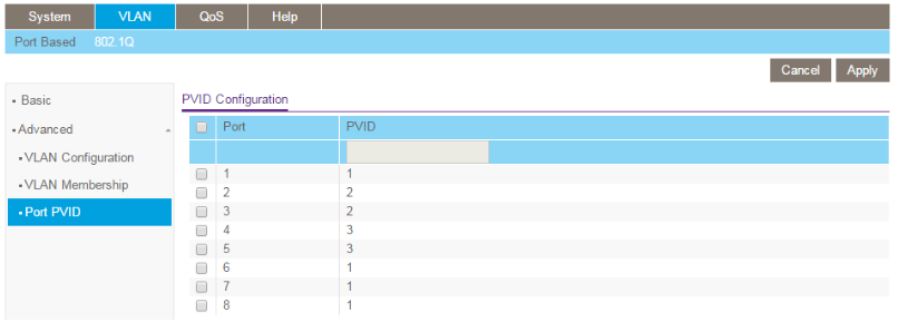
- Go to VLAN > 802.1Q > Advanced > Port PVID.
- Set the PVID of that port to the VLAN ID it was assigned to.
- For example, you will set the 2nd and 3rd ports with PVIS of 2 and then click Save.
- In the same manner, set ports 4 as well as 5 with a PVID of 3 and hit Apply.
- The PVID configuration will look like this.
Create VLAN on the Router
- Open a new tab on your web browser or probably open another one altogether.
- Enter the IP address of the router that you are using and hit the Enter key.
- Soon you will have to insert the username (admin) and password (password).
- Click the Login button and go to Network Configuration.
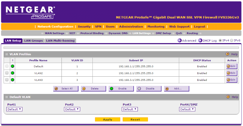
- Once done, select LAN Settings > LAN Setup.
- Click Add under the VLAN Profiles section.
- Enter the required details of VLAN 2 and then click the Apply button.
- When you return to the LAN Setup page, add another VLAN Profile.
- This can be done if you click the ADD button.
- Enable the details for VLAN 3 and select Save.
- In a flash, the LAN Setup page will look similar to the image below.
Testing is Required Now
- Connect a PC to a port on the switch in VLAN 2.
- Disable the connection on both your client devices, i.e. both your computers.
- Check that the computers cannot access each other.
- Ensure that your client device is able to access the internet with ease.
- Connect the PC to a port on the switch in VLAN 3.
It is recommended that you do not skip even one step given above. In case you do not take this precaution, then you will not be able to protect yourself from getting stuck.
Conclusion
This was all about the information related to Netgear VLAN configuration on a web managed plus switch with shared access to the internet. We expect that this blog post helped you to achieve what you came here for. In case it did, and compelled you to gain knowledge regarding similar topics in the future, it is recommended you bookmark this post. We are suggesting you this because every single time that you wish to satisfy your immense hunger for knowledge, you will be able to find something latest.